Calibrating a video for measurement in VidSync
Overview
A core purpose of VidSync is to allow measurement in real units based on video footage. Calibration is necessary to give the program a frame of reference for the real-world coordinates of objects on the video.
The calibration process described on this page does not account for the effects of radial distortion (typically barrel distortion), the “bulging” look that is typically associated with fisheye lenses but is present in almost all lenses to a sublte degree that can affect measurements. Distortion is corrected in VidSync through the separate Distortion correction process before calibration.
Calibration hardware
Calibration requires a “calibration frame” with two parallel planes, one behind the other, expressed in a common coordinate system. See the Hardware page for details. It is possible in some setups to have a 3-D frame with different sets of planes for each camera, e.g. one camera looking into an aquarium from the front and another from the side. This still works if the points on all the planes are known in the same 3-D coordinate system.
In the field (or lab)
You’ll want to film the calibration frame from an angle such that both cameras can see many points on both the front and back faces, and they take up a reasonably large portion of the screen in both cameras. They do not need to be able to see the same set of points, as long as they can identify which of the points on the overall frame they’re seeing, within the same overall coordinate system.
Entering the calibration frame information into VidSync
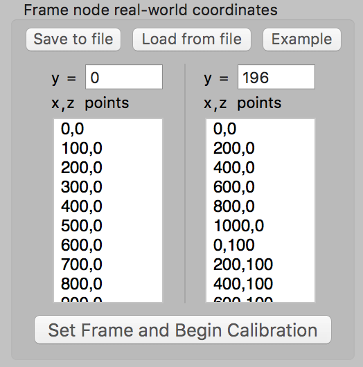
The first time you use VidSync with a new calibration frame, you need to enter the real-world coordinates of each dot on the frame into the “Frame node real-world coordinates” section of the Calibration tab. You can configure which surfaces are x, y, and z, but by default the horizintal direction is x, vertical is z, and the direction separating the frame faces is y. Enter them in an easy-to-remember order, such as from left to right, then bottom to top.

If you’re comfortable with programming, it’s pretty easy to write code to generate these point lists instead of typing them out manually. Here’s an example from Mathematica:
frameWidth = 1000;
frameHeight = 500;
vSpacing = 100;
hSpacing = 100;

MyToString[n_] := If[n == 0, ToString@IntegerPart@0, ToString@n];

StringJoin@
 Flatten[Transpose@
   Table[MyToString@x <> "," <> MyToString@z <> "\n", {x, 0,
     frameWidth, hSpacing}, {z, 0, frameHeight,
     vSpacing}], 1]
Before calibrating a video clip, the user enters the distance between the calibration frame faces and a list of physical 2-D coordinates of the nodes on each face of the calibration frame. The length units in which these node coordinates are provided become the measurement and output units for VidSync. The user can optionally customize the coordinate axes (x, y, and z) corresponding to each face of the frame, for example, to tell the program if a top-view camera and a side-view camera are looking through different, perpendicular faces of the frame. These frame descriptions can be saved as a separate file and reloaded for any other video filmed with the same calibration frame.The user begins calibration by finding a synchronized timecode at which all cameras have a clear view of the calibration frame, and the frame and cameras are both as motionless as possible. A button click loads the frame node coordinates into a table matching them with (so far, blank) screen coordinates. Screen coordinates are recorded by clicking on the center of each node. If a node center is unclear due to poor visibility, it can and should be deleted from the list, because visual guesswork increases error. Throughout this process, each point’s matched 3-D coordinates are overlaid on the video, so mistaken correspondences are easy to detect. Once the user completes this process for the front and back faces of the frame in one camera, VidSync calculates the projection matrices, and the calibration of that camera is complete. Each camera is calibrated separately in the same manner. Using two cameras and a 5-by-4 node calibration frame, a typical calibration takes 5 to 10 minutes. Completed calibrations can be saved as separate files and reused for other videos shot with the cameras in the same relative orientation.