Hardware design for VidSync
The two main pieces of hardware required to use VidSync (which can be combined into one) are a chessboard-like pattern to provide information for radial distortion correction, and the “calibration frame” which provides 3-D coordinates. They’re described on this page. The separate video cameras and mounts page discusses considerations regarding the choice of video cameras and how to mount them together.
Distortion correction chessboard
The chessboard pattern should be a stiff, flat material printed with black and white squares with precisely aligned corners, large enough to fill the screen when positioned far enough from the cameras to be in focus when the focus is set for filming fish. The squares should be large enough to be distinct from one another at that distance, and small enough that each plumbline comprises a large number of points. Use of a professional sign printer is recommended to obtain a precise, waterproof grid.
Calibration frame
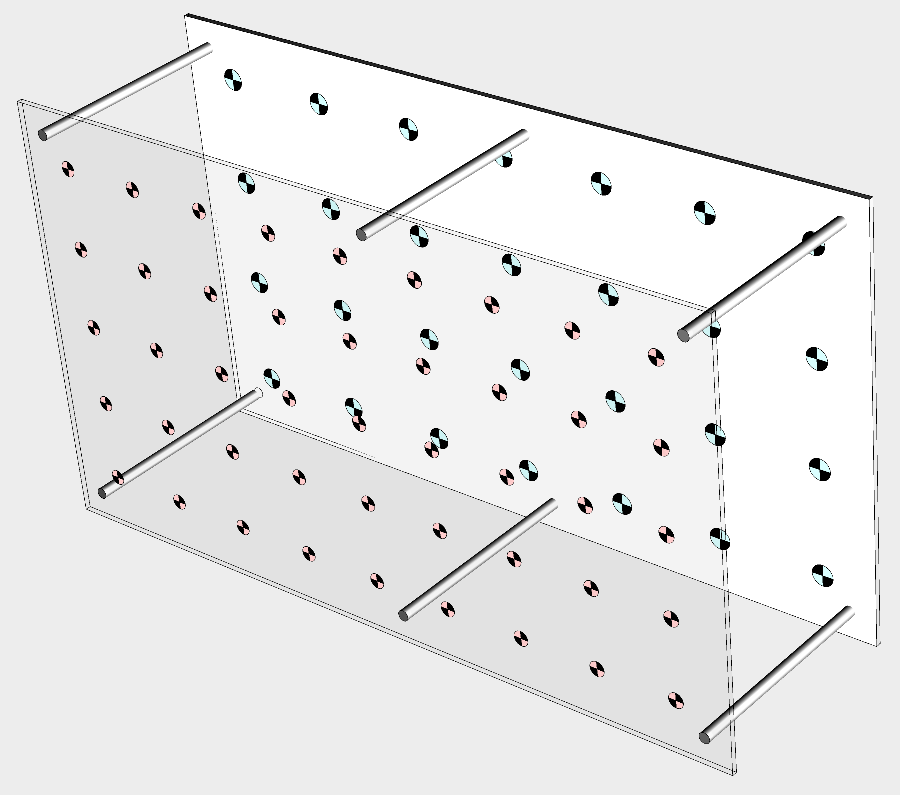
The calibration frame is the device that gives VidSync the information to reconstruct a 3-D space from clicks on a 2-D computer screen. Many possible designs will work, but a suggested version looks something like this:

The different colors to make it easier to distinguish between front and back surface points are minor and optional.
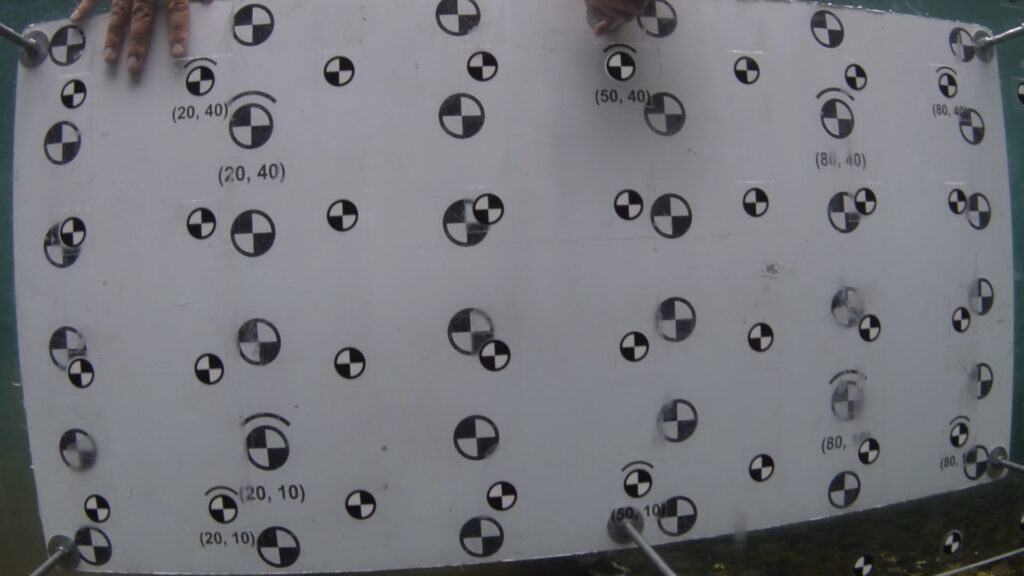
Here’s a video still of a real calibration frame using this basic design in an Alaskan river. The coordinates printed in front of some of the dots make it much easier to tell which ones are which when digitizing the calibration on the computer.

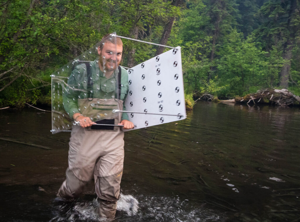
Earlier in this same project we were using a version of this frame with the faces separated farther apart. Below my awesome 2015-2016 technician Josh carries the frame back from calibrating in an Alaskan spring creek. We found that the closer separation provided better accuracy in this study due to the dot fields on the back face taking up more of the screen and requiring less extrapolation, but other studies have potentially found the opposite, perhaps because their cameras involved less inherent distortion than ours. It’s a variable worth experimenting with on a per-application basis when very high accuracy is paramount, but both designs worked relatively well for most purposes.

Conceptual requirements
Many calibration frame designs are possible in principle, and you can read this section to understand the possibilities and tradeoffs involved. For a simple design that will work for many studies, see the next section.
The calibration frame must consist of at least one pair of precisely parallel planes, separated by a distance that must be meticulously measured, because it is VidSync’s only source of information on the scaling of that dimension. Each plane is marked at four or more points, called nodes, at known 3-D coordinates. Typically something like 20-50 nodes per surface are used. Although it is not mandatory to do so, nodes are typically located on a regular grid for simplicity. It is also convenient for each node to be a checkered pattern, because this allows very precise location of its center.
Variations on this theme are suited for different settings, including cage-like grids of rods or dots painted on the sides of an aquarium. A calibration frame may have points on only two surfaces if both cameras are to look through it from one side, as in a typical stereo camera system. Alternatively, it may have dots on four surfaces, such as in a laboratory with a side-view camera and a top-view camera. In general, the cameras need not be aimed at the same nodes, as long as all node positions are known in the same 3-D coordinate system and each camera has a clear view of two parallel surfaces. To be able to tell which nodes are which when looking at a partial view of the frame surface (which is often the case for the face closest to the cameras) it is useful to have some sort of distinct markigns, whether irregular shapes at known positions or actual printed coordinates next to selected nodes. Different cameras are often calibrated with a slightly different selection of nodes because debris or lighting obscures some of them; this is not a problem as long as enough other nodes remain visible that the calibration result is not overly sensitive to errors digitizing any single node.
The optimal calibration frame design for any given project depends on expected subject distance, camera focal length, and the relative positions and orientation of the cameras. Ideally, the frame should be large enough to span most of the screen in each camera when it is located at the same distance from the cameras as the expected measurement subjects. For distances of several meters this is impractical, and there is a tradeoff between screen coverage and matching the expected subject distance. Our results show that extrapolating outside a small frame close to the cameras is possible with minor errors, but filming a frame too far away to fill most of the screen creates larger errors, so this tradeoff should be resolved in favor of screen coverage.
Practical design and materials
The easiest way to build the design pictured above is using two large sheets of polycarbonate (brand names such as Lexan or Makrolon). The patterns can be built using a graphics program like Photoshop or Illustrator with precise dimensions (or see below for templates), or mathematical software like Mathematica, and then printed by a professional printer on an adhesive material.
For the adhesive material, I have successfully used 4 Mil Clear Gloss Permanent Adhesive Vinyl (front surface) and white 4 Mil Matte Adhesive Vinyl (back surface) from aprintco.com, but many printing companies surely offer similar products and we do not intend to endorse any particular one. Furthermore, there were problems with using clear vinyl and I would not necessarily recommend that in the future. The “white” quarters of the checkered dots are transparent on clear vinyl, making it necessary to put some white backing (we use 0.875″ white adhesive dots on weatherproof polyester paper from onlinelabels.com for this) to produce black-and-white dots. Also, although the vinyl appears clear when resting directly on top of a surface (for which it is designed), it does not transmit a clear image from a distance, meaning the back surface dots were nearly invisible (or extremely blurred) through the clear vinyl on the front surface. Thus we had to cut out around each dot on the front surface with a razor blade, then peel off all the clear vinyl except what was holding the dots in place. Given that this cut-out step is necessary anyway, it would be easier to print the whole front surface on white vinyl and cut and peel it around the dots.
The checkerboard pattern for distortion correction can be printed on back side of the back polycarbonate face, so the same device can be used (and just flipped around) for each step.
The rods separating the front and back polycarbonate faces can easily be made by purchasing some threaded aluminum rod (I have used 3/8″ threaded T6061 aluminum) and using a series of nuts, washers, wing nuts, and lock washers to fix the surfaces in place (from inside to outside: hex nut, washer, polycarbonate, washer, lock washer, wing nut). Rods in the four corners may work for small frames, but large frames (50+ cm wide) benefit in stability from another set of rods in the center of the frame as shown on the diagram. After fixing the distance surfaces the faces at the desired value (20 cm for example), you can use threadlocker to fix the inner hex nuts in place for quick, easy disassembly and reassembly.
To assure that the back face dots are located straight behind the corresponding coordinates on the front face, you can lay the clear front face (after cutting out around all the nodes) on top of the back face, line up the checkered centers of the dots perfectly, and clamp them together tightly. Keep them clamped in this same way while drilling all the holes for the threaded rods.
One problem with using a front grid mounted on clear polycarbonate is that the material refracts the images of the dots on the back surface, altering their apparent positions very slightly. This can significantly affect measurements, particularly at long distances. VidSync includes a correction for this effect (available via a button on the “back surface” calibration tab), based on the material thickness and published refractive index.
Download printable templates
Here are two downloadable templates we have used to develop calibration frames for fieldwork.
Calibration Frame 100x50cm.zip – Ideal for fairly wide camera separations or extremely wide-angle lenses. Slightly cumbersome to tote around.
Calibration Frame 80x40cm.zip – Ideal for most GoPro applications unless the separation between cameras is extremely wide for long-distance measurement.
Before applying one of these in the field, make sure it actually was printed true-to-size and the separation between points is as expected. If the printer somehow made it larger or shrank it, you can still use it, but you will have to enter the actual coordinates of the points into VidSync instead of the intended ones that fall on neat 10-20 cm intervals.